

 Domestic fans
  Industrial and commercial fans
  Single-room ventilation systems with heat recovery
  Air handling units
  Air heating systems
  Air sterilizers
  Smoke extraction and ventilation
  Accessories for ventilating systems
  Electrical accessories
  Ventilation ducts and fittings
  Air distribution components
  Ventilation kits and vents
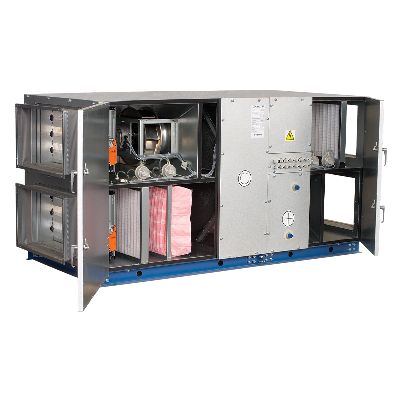
 VENTS AVU 03/SE/R/O

- Description
- Characteristics
- Downloads
- Dimensions
- Additional diagrams
- Legend
Description
Description
| DESCRIPTION | CASING |
|
|
| MODIFICATIONS | FILTERS |
|
|
| ROTARY REGENERATOR | |
| MOTOR |
|
|
|
 |
|
| Rotary regenerator operating logic | |
| HEATER | CONTROL AND AUTOMATION |
|
|
| AUTOMATION FUNCTIONS: | |
|
|
| COOLER | |
|
|
| MOUNTING | |
|
|
Characteristics
Characteristics
| Parameter |
AVU 03/SE/R/O |
Measurement unit |
|---|---|---|
| Frequency | 50 | Hz |
| Engine Type | 380В / 50Гц | - |
| Phase | 3 | ˜ |
| Maximum unit power | 2520 | W |
Unit voltage  |
400 | V |
| Maximum air capacity | 3000 | m³/h |
| Maximum unit current | 4 | A |
| Casing material | aluzinc | - |
|
Maximum transported air temperature |
-25 +60 | °С |
| Insulation | 50 mm, mineral wool | - |
| Filter: extract | кассетный G4 | - |
| Filter: supply | кассетный G4 и карманный F7 | - |
| Connected air duct size | 600х350 | mm |
|
Heat recovery efficiency |
65 | % |
| Heat exchanger material | алюминий | - |
|
Heat recovery |
1 | - |
|
Water cooler block (not included delivery) |
C3/AVU 03/О | - |
|
DX cooler block (not included delivery) |
DX3/AVU 03/О | - |
Files archieve
Downloads
Select document type
Dimensions
Characteristics
| Parameter | Value | Measurement unit |
|---|---|---|
| Length | 2200 | mm |
| Width | 970 | mm |
| Height | 970 | mm |
Additional diagrams
Additional diagrams
Water heater parameters:

Water heater parameters calculation example:
Air Speed. Starting from 3500 m3/h on the air flow scale draw a vertical line 1 till the air speed axis which makes 4.65 m/s..
- Supply air temperature. Prolong the line 1 of air flow up to the point where it crosses the outside air temperature (-10°C); then draw a horizontal line 2 from this point to the left till crossing water in/out temperature curve (90/70). From this point draw a vertical line 3 to the supply air temperature axis on top of the graphic (+22.5 °C).
- Heating capacity. Prolong the line 1 up to the point where it crosses the outside air temperature (red line, -10°C) and draw a horizontal line 4 from this point to the right until it crosses water in/out temperature curve (90/70), from here draw a vertical line 5 up to the scale representing the heating coil capacity (42.0 kW).
- Water flow. Prolong the line down to water flow axis at the bottom of the graphic 6 (0.5 l/s).
- Water pressure drop. Draw the line 7 from the point where line 6 crosses the black curve to the pressure drop axis. (6.5 kPa).
Water cooler parameters:

Water cooler parameters calculation example:
Air Speed. Starting from 2850 m3/h on the air flow scale draw a vertical line 1 till the air speed axis which makes 3.85 m/s.
- Supply air temperature. Prolong the line 1 of air flow up to the point where it crosses the outside summer air temperature (+32°C); then draw a horizontal line 2 from this point to the left till crossing intake air humidity curve (50%). From this point draw a vertical line 3 to the air temperature downstream of the cooler axis on top of the graphic (+20.7 °C).
- Cooling capacity. Prolong the line 1 up to the point where it crosses the summer outside air temperature (+32°C) and draw a horizontal line 4 from this point to the right till crossing intake air humidity curve (50%), from here draw a vertical line 5 up to the scale representing the cooling coil capacity (19.8 kW).
- Water flow. Prolong the perpendicular line down to water flow axis at the bottom of the graphic 6 (0.78 l/s).
- Water pressure drop. Draw the line 7 rightwards from the point where the line 6 crosses the curve to the pressure drop axis. (30 kPa).
DX cooler parameters calculation example:

DX cooler parameters calculation example:
Air Speed. Starting from 3500 m3/h on the air flow scale draw a vertical line 1 till the air speed axis which makes 4.65 m/s.
- Supply air temperature. Prolong the line 1 of air flow up to the point where it crosses the outside summer air temperature (+30°C); then draw a horizontal line 2 from this point to the left till crossing intake air humidity curve (50%). From this point draw a vertical line 3 to the air temperature downstream of the cooler axis on top of the graphic (+22.5 °C).
- Cooling capacity. Prolong the line 1 up to the point where it crosses the summer outside air temperature (+30°C) and draw a horizontal line 4 from this point to the right till crossing intake air humidity curve (50%), from here draw a vertical line 5 up to the scale representing the cooling coil capacity (14.5 kW).
- Coolant flow. Prolong the perpendicular line down to coolant flow axis at the bottom of the graphic 6 (310 kg/hr).
- Coolant pressure drop. Draw the perpendicular line 7 rightwards from the point where the line 6 crosses the curve to the pressure drop axis. (24.0 kPa).
Legend
Legend
| Series | Rated air capacity [m3/h] | Heat exchanger | Function block | |||
|---|---|---|---|---|---|---|
| VENTS AVU | 03 - 3000 m3/h |
SE/R - rotary regenerator, inner modification; SE/R /О - rotary regenerator, outer modification. |
H - water heater |
