Domestic fans
  Industrial and commercial fans
  Single-room ventilation systems with heat recovery
  Air handling units
  Air heating systems
  Air sterilizers
  Smoke extraction and ventilation
  Accessories for ventilating systems
  Electrical accessories
  Ventilation ducts and fittings
  Air distribution components
  Ventilation kits and vents
 VENTS NKV 160-4

- Description
- Characteristics
- Downloads
- Dimensions
- Additional diagrams
- Legend
| APPLICATIONS |
|
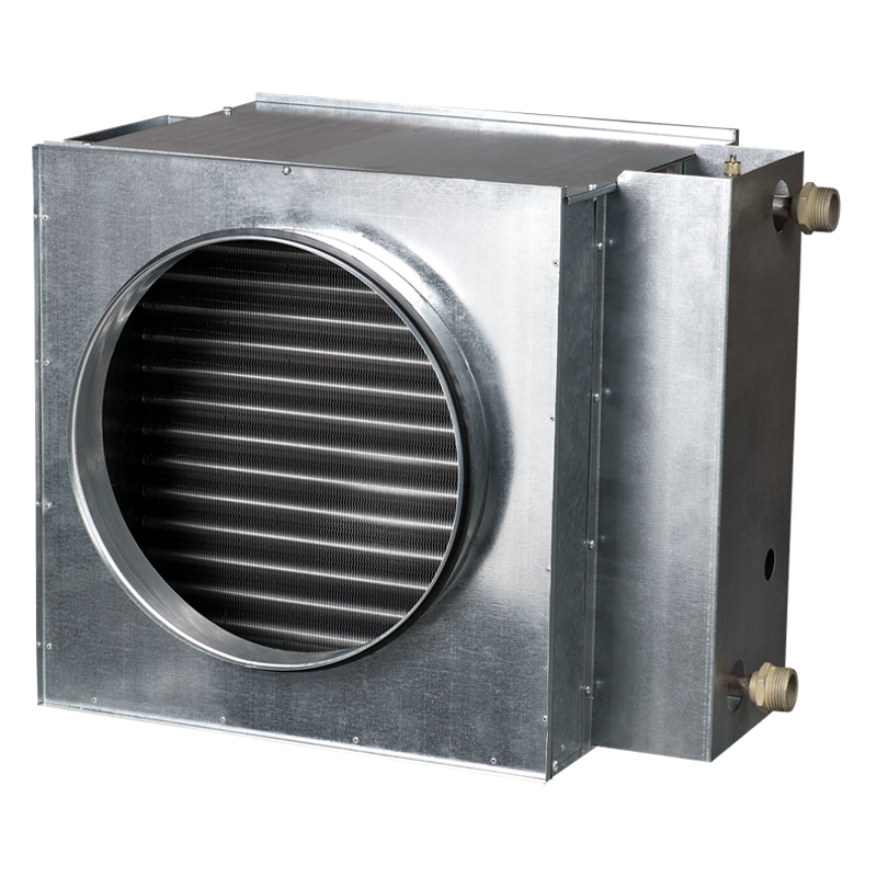
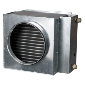
Duct water heaters are designed for heating of supply air in round ventilation systems. They can be also applied in supply or supply and exhaust ventilating units. |
| DESIGN |
|
The heater casing is made of galvanized steel, the tubular coils are of copper tubes and the heat exchange surface is made of aluminium plates. The heaters are equipped with rubber seals for airtight connection to the air ducts. The heaters are ailable in 2 and 4 rows modifications and are designed for maximum operating pressure 1.6 MPa (16 bar) and maximum water operating temperature +100°С. The outlet manifold has a branch pipe for installation of submersible temperature probe or icing protecting device. The heater is equipped with a nipple for the system deaeration. |
| MOUNTING |
|
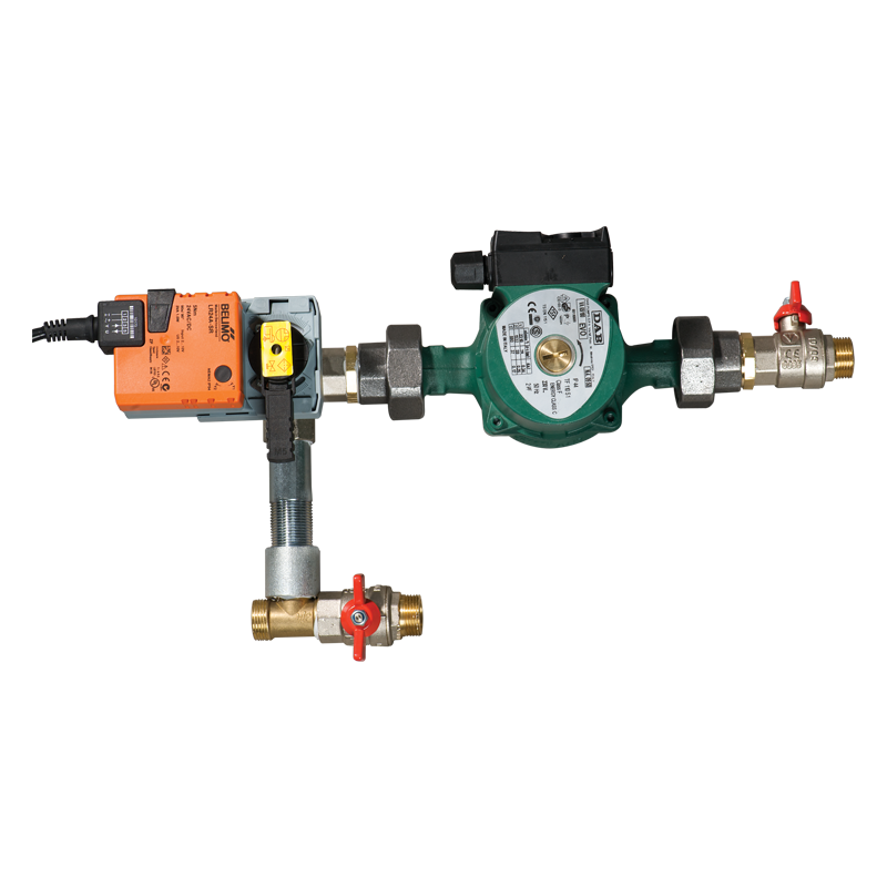
The heater design ensures its mounting on the round ducts in any position by means of clamps. The water heating coils can be installed in any position that enables the heater deaeration. The air flow direction shall match the pointer designation on the heater. The mounting shall be performed in such a way as to enable the uniform air stream distribution along the whole cross section. The air filter shall be installed at the heater inlet to protect the heating elements against pollution. The heater can be installed at the fan inlet ot outlet. If the heater is located at the filter outlet the air duct between the heater and the filter shall have the length of at least two connecting diameters to ensure the air flow stabilization as well as permissible air temperature level inside the fan. The heater shall be connected on the counterflow principle, otherwise its efficiency can drop by 5-15%. All the nomographic charts in the catalogue are valid for such connection. If water serves as a heat medium the heaters are suitable for indoor installation only. For outdoor installation use antifreeze mixture, i.e. ethylene glycol solution. To ensure the correct and safe heater operation use the automation system that provides complex control and freezing protection:
|
 |
 |
| Connection against air flow | Connection along air flow |
Air pressure loss for water heaters
NKV round series

| Parameter |
NKV 160-4 |
Measurement unit |
|---|---|---|
| Weight | 8.2 | kg |
Number of water coil rows  |
4 | - |
|
Round duct size |
160 | mm |
| Heating | water heating | - |
| Duct | for round air ducts | - |
| Connection diameter | 160 | mm |
| Parameter | Value | Measurement unit |
|---|---|---|
| ∅D | 159 | mm |
| B | 400 | mm |
| H | 280 | mm |
|
H3
|
200 | mm |
| L | 300 | mm |
| L1 | 28 | mm |
|
L2
|
65 | mm |
|
L3
|
220 | mm |
|
K
|
G 3/4'' | mm |

How to use water heater diagrams:
Air Speed. Starting from 700 m3/h on the air flow scale draw a vertical line 1 till the air speed axis which makes about 4.4 m/s.
- Supply air temperature. Prolong the line 1 up to the point where it crosses the outside air temperature (blue curve), e.g. -25°C; then draw a horizontal line 2 from this point to the left till crossing water in/out temperature curve (70/50 °C). From this point draw a vertical line 3 to the supply air temperature axis on top of the graphic (+26 °C).
- Heating coil capacity. Prolong the line 1 up to the point where it crosses the outside air temperature indicated as red curve (e.g., -25°С) and draw a horizontal line 4 from this point to the right to the intersection of water in/out temperature curve (e.g., 70/50 °С). From this point draw a vertical line 5 up to the scale of heating coil capacity (13.0 kW).
- Water flow. Prolong the line 6 down to water flow axis at the bottom of the graphic (0.16 l/s).
- Water pressure drop. Draw the line 7 from the point where line 6 crosses the black curve to the pressure drop axis. (15 kPa).
| Series | Flange diameter [mm] | Number of water coil rows | ||
|---|---|---|---|---|
|
NKV |
100; 125; 150; 160; 200; 250; 315 | 2;4 |