

 Domestic fans
  Industrial and commercial fans
  Single-room ventilation systems with heat recovery
  Air handling units
  Air heating systems
  Air sterilizers
  Smoke extraction and ventilation
  Accessories for ventilating systems
  Electrical accessories
  Ventilation ducts and fittings
  Air distribution components
  Ventilation kits and vents
 VENTS USWK 1-10

- Description
- Characteristics
- Downloads
- Dimensions
- Wiring plan
- Additional diagrams
- Legend
| APPLICATION |
|
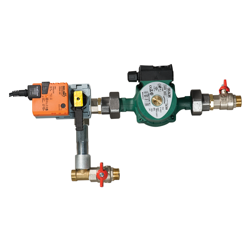
The mixing unit USWK is designed for smooth heat medium flow control in ventilation systems equipped with water heaters or coolers for supply air temperature regulation. The mixing unit controls heat medium flow supplied to the water heat exchanger and in such a way maintains the supply air temperature. The mixing unit USWK is compatible with NKV water heaters, duct coolers OKW as well as all water heat exchangers (both heaters and coolers) integrated into air handling units. |
| DESIGN AND OPERATING LOGIC |
|
Design of the mixing unit USWK is shown in fig. 1. The circulation pump (1) of the mixing unit ensures ongoing heat medium circulation through the water heat exchanger. The heat medium regulating three-way valve (3) with electric actuator (2) is installed before the circulation pump to mix the water supplied from the heating (cooling) system with the return water supplied through the recirculation pipe (4). The three-way valve is designed to provide the mixing ratio of two water streams and thus to control the heat medium temperature supplied to the water heat exchanger. The three-way valve actuator is controlled by 0-10 V output signal from the ventilation control system.
|
| CONNECTION TO WATER MAINS |
|
The mixing set is connected directly to the water heat exchanger and water mains through rigid and/or flexible pipes. In case of flexible pipe connection, fix the mixing unit firmly to the wall or another rigid surface with clapms. While installing the mixing set keep the motor horizontal position to disable any distortions and mechanical loads from the connected pipelines to USWK unit. While connecting the mixing set to water mains make sure of no loads and distortions that may damage the unit structure and provoke USWK airtightness breach. While connecting the pipelines ensure their quick detachment for scheduledf servicing and maintenance operations. |
| ELECTRIC CONNECTION |
|
All electric connections are allowed by qualified electricians with valid permit for electric operations. Before connecting the pump make sure to have grounded it. Make steps to prevent contact with power cables. |
| OPERATING CONDITIONS |
|
The pump motor bearings are greased by the pumped medium. The single-phase pumps do not require extra overload protection and the three-phase pumps must be provided with external overload protection. The maximum allowable heat medium pressure in the unit is 10 bar. |
| 3-WAY VALVE |
|
3-way valve |


| Parameter |
USWK 1-10 |
Measurement unit |
|---|---|---|
Three-way valve Kvs  |
10 | - |
|
Connecting diameter |
1'' | mm |
|
Circulating pump |
- | |
|
Three-way valve regulation mode |
Smooth 0…10 V |
- |
|
Three-way valve with electric actuator |
Belimo R323 |
- |
|
Three-way valve actuator |
Belimo LR24A-SR |
- |
|
Connection |
Резьбовое | - |
|
Three-way valve nominal diameter |
DN 25 | - |
|
Maximum capacity |
6 | m³/h |
|
Maximum developed head |
57 | - |
|
Pumped medium temperature |
-10 +110 | °С |
|
Maximum glycol content in pumped medium |
30 | - |
|
Number of pump speeds |
3 | - |
|
Phase |
1 | - |
|
Maximum pump power |
184 | W |
|
Pump voltage |
230 | V |
| Weight | 6.8 | kg |
| Parameter | Value | Measurement unit |
|---|---|---|
| B | 175 | mm |
| H | 320 | mm |
| H1 | 210 | mm |
| L | 490 | mm |

Т1 and Т2 - supply and return pipeline;
Р1 and Р2 - manometers for supply and return pipelines in the water mains;
1 - USWK (mixing set);
2 - Water heater;
3 - Three-way valve with actuator;
4 - Circulation pump;
5 - Shutoff valve;
6 - Supply and return pipeline from water mains to the water heater;
7 - Non-return valve;
8 - Balancing valve;
9 - Coarse filter.
To select the mixing set according to the nomographic chart, calculate the required heat medium flow through the water heat exchanger and water pressure drop (water head). These parameters are calculated according to the heating/cooling diagrams specifically for each water heat exchanger stated specifically herein.

| Series | Connecting diameter | 3-way valve, Кvs | ||
|---|---|---|---|---|
|
USWK |
3/4''; 1''; 1 1/4''; 1 1/2''; 2'' | 4; 6; 10; 16; 25; 40 |
