Domestic fans
  Industrial and commercial fans
  Single-room ventilation systems with heat recovery
  Air handling units
  Air heating systems
  Air sterilizers
  Smoke extraction and ventilation
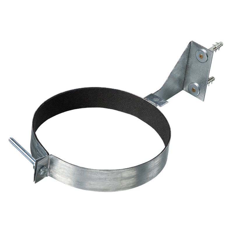
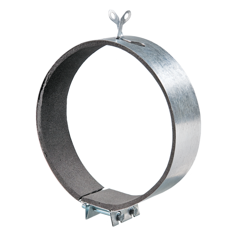
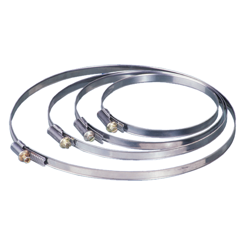
  Accessories for ventilating systems
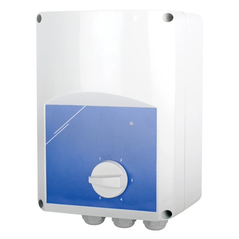
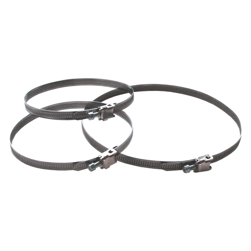
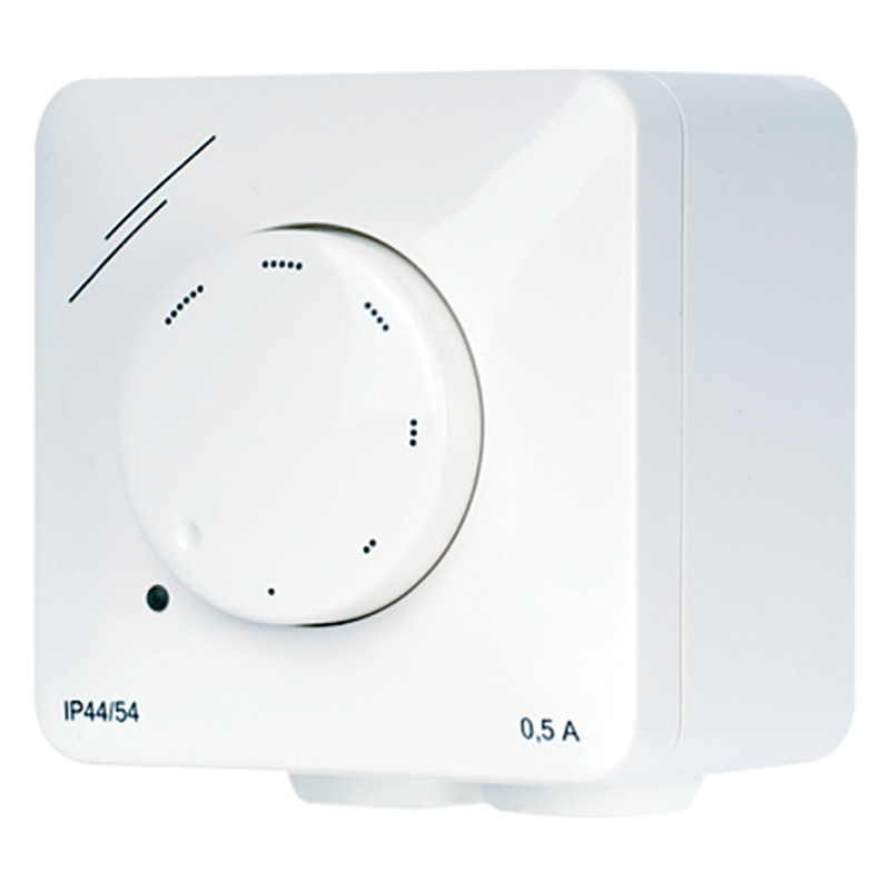
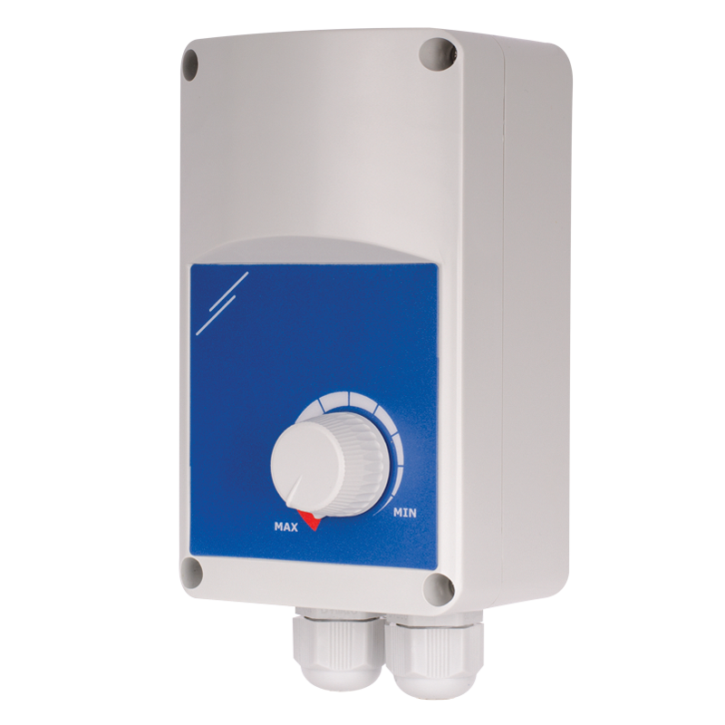
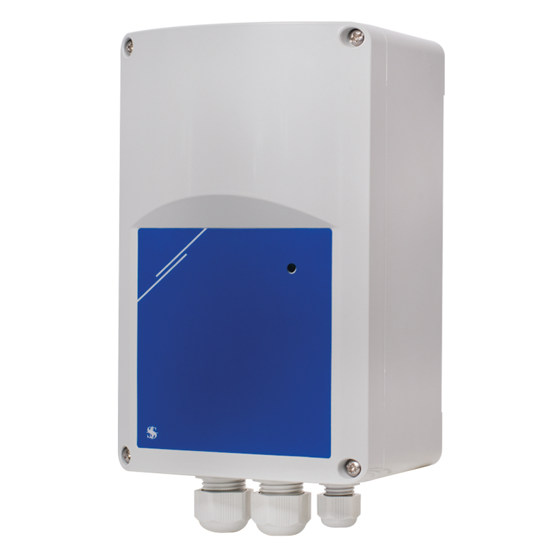
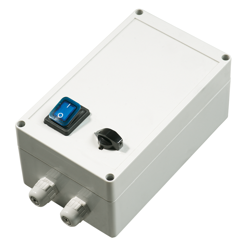
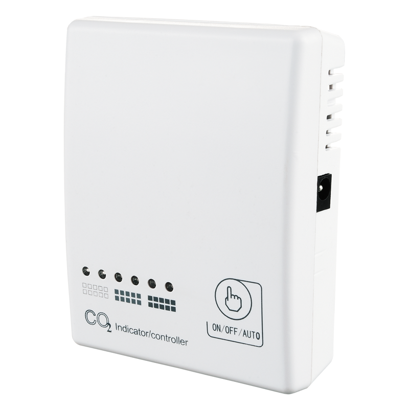
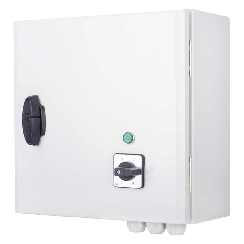
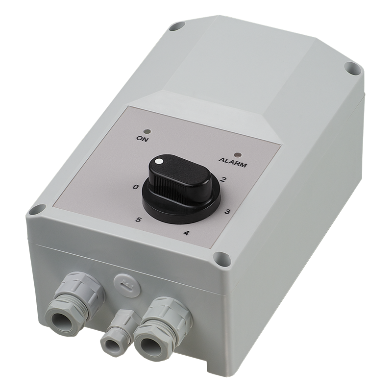
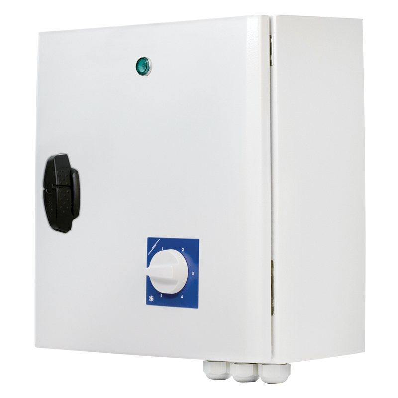
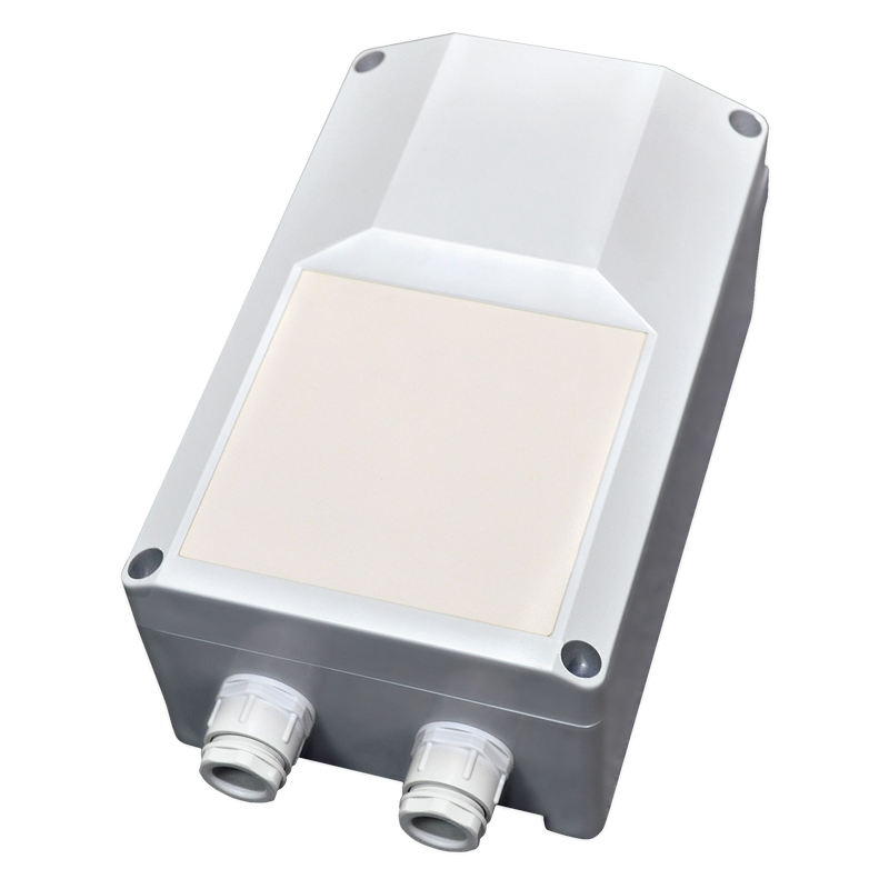
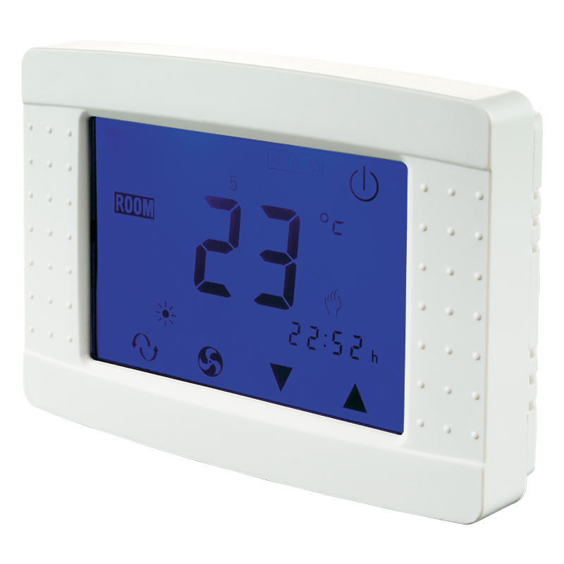
  Electrical accessories
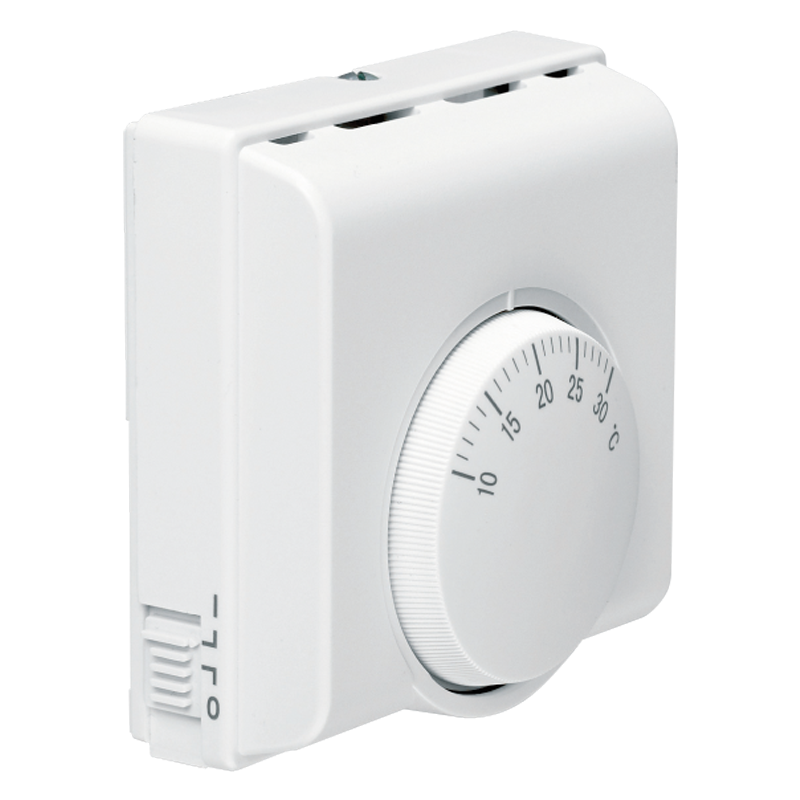
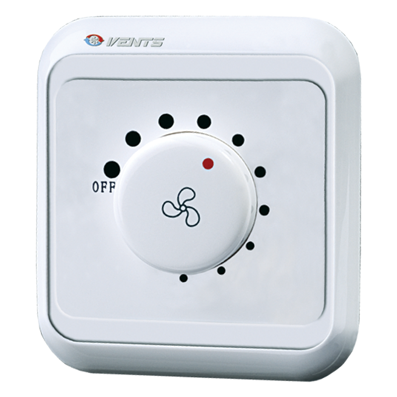
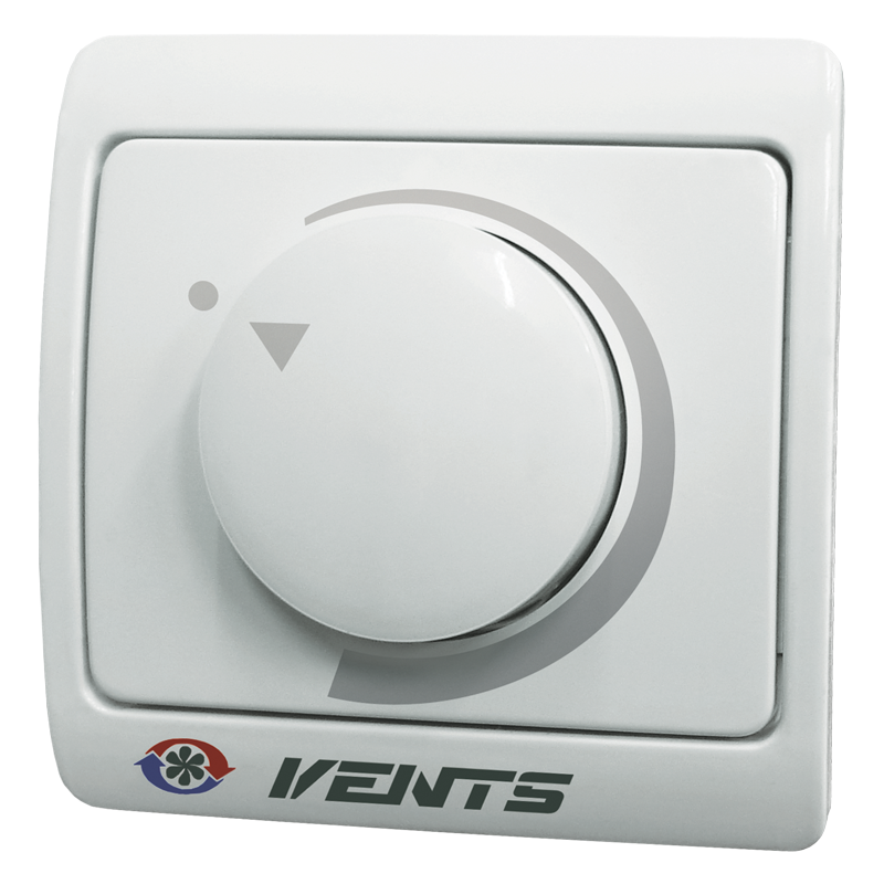
  Ventilation ducts and fittings
  Air distribution components
  Ventilation kits and vents
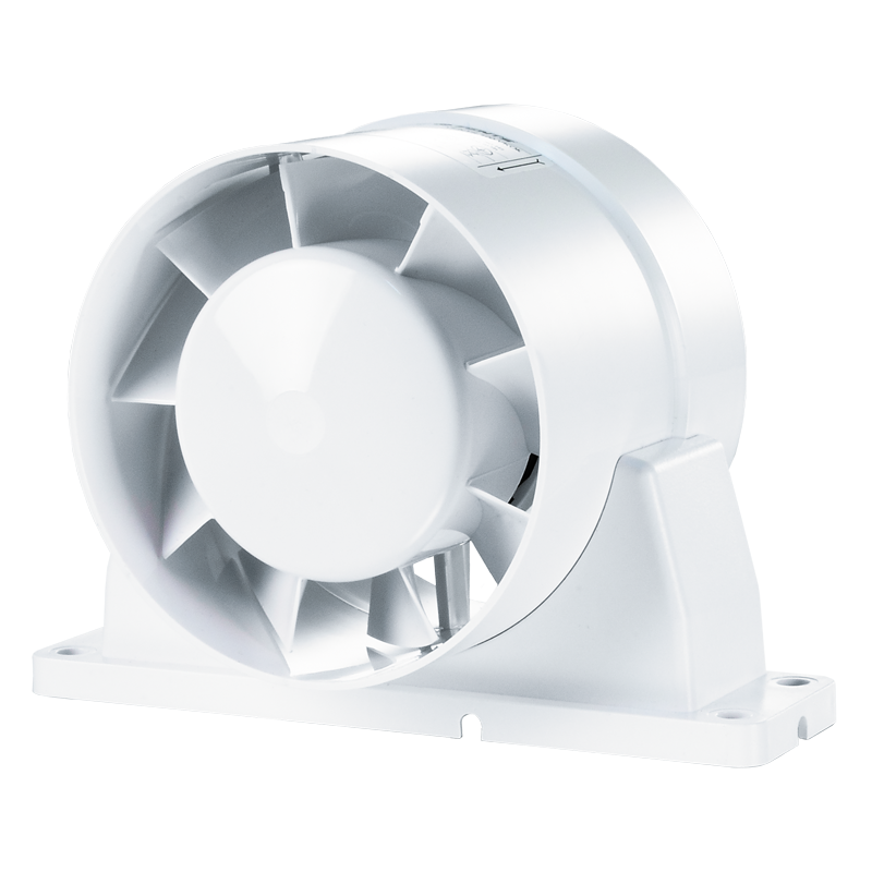
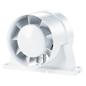
 VENTS 125 VKOk

- Description
- Characteristics
- Downloads
- Modifications
- Dimensions
- Wiring plan
- Legend
- Example of installation
- BIM
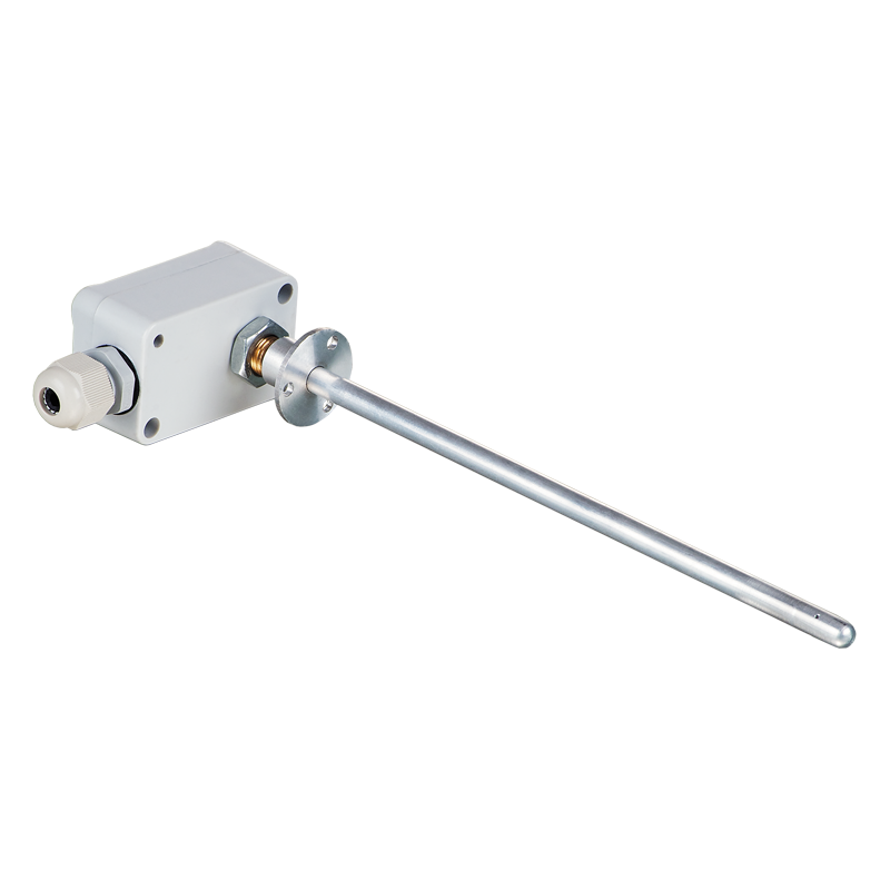
Description
Description
| APPLICATIONS | |
|
|
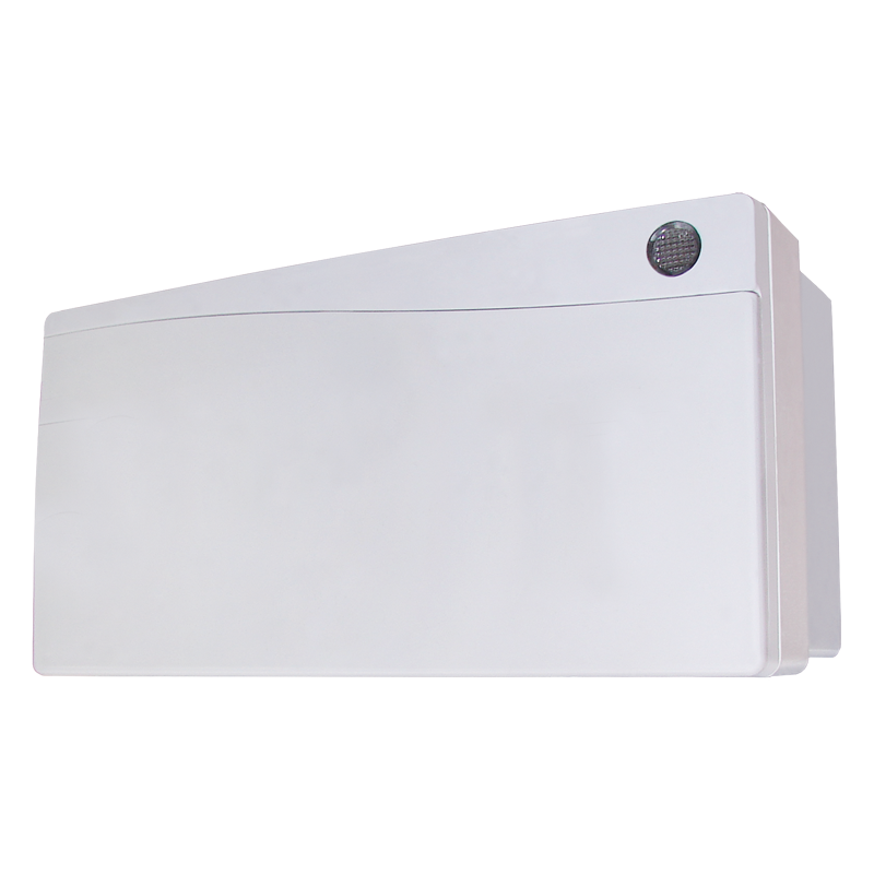
| DESIGN | |
|
|
| MOTOR | |
|
|
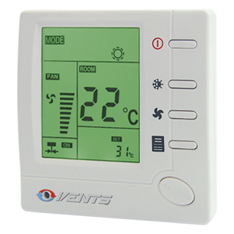
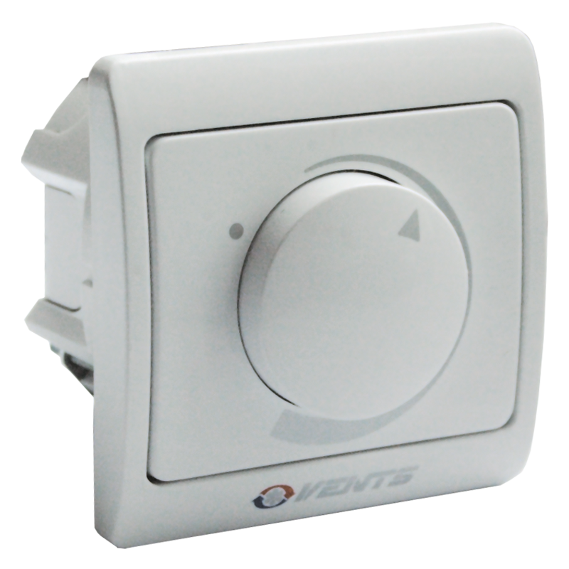
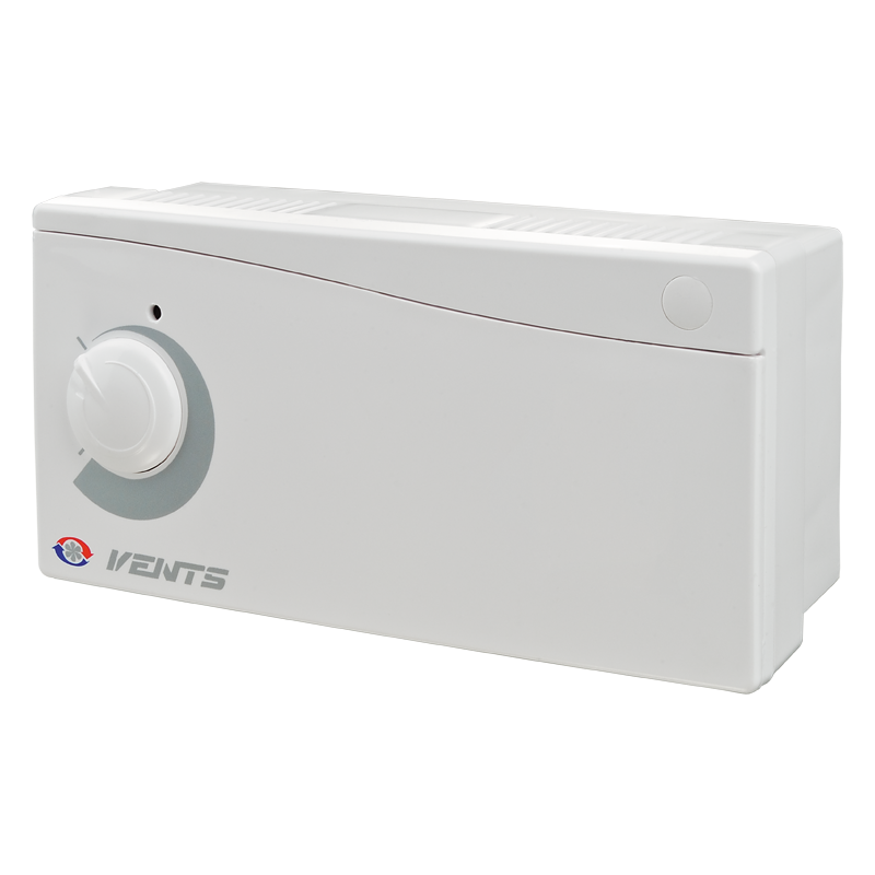
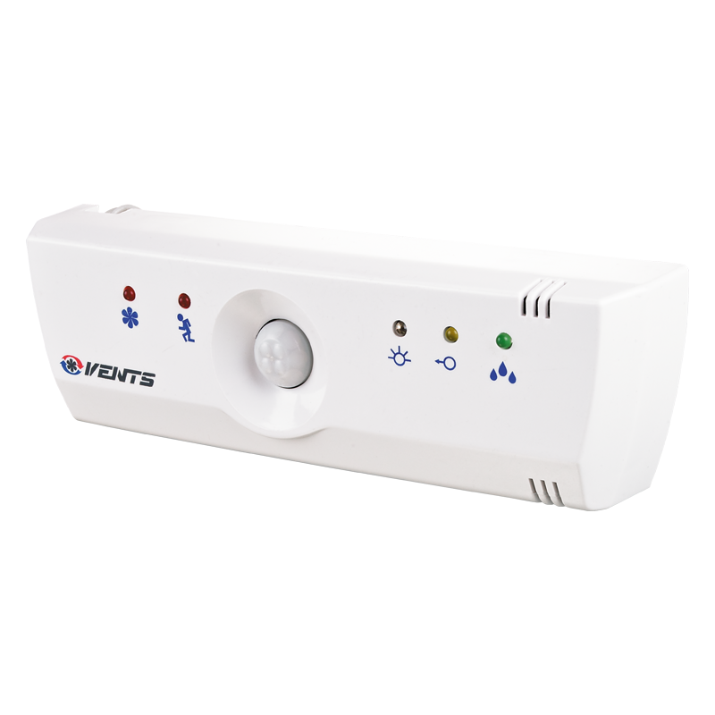
| CONTROL | |
| Manual: | Automatic: |
|
|
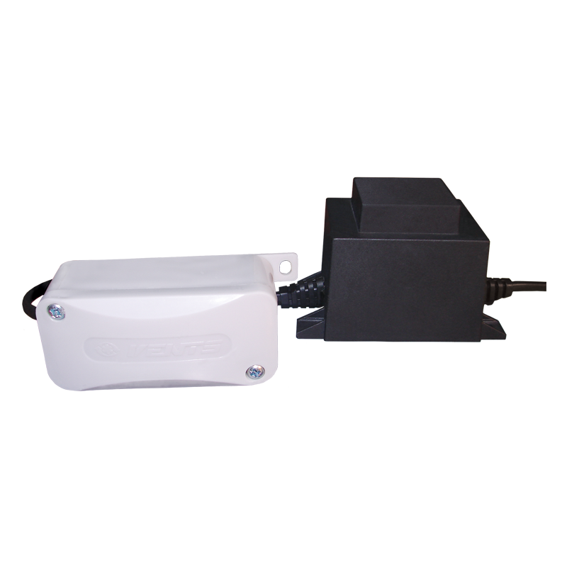
| MOUNTING FEATURES | |
|
|
 |
|||||
| VENTS VKO fan flat ventilation example | VENTS VKOk fan cottage ventilation example | ||||
Characteristics
Characteristics
| Parameter |
VENTS 125 VKOk |
VENTS 125 VKOk L |
Measurement unit |
|---|---|---|---|
| Voltage | 220-240 | 220-240 | V |
| Frequency | 50/60 | 50/60 | Hz |
| Power consumption | 16 | 16 | W |
| Air capacity | 185 | 185 | m³/h |
| Current | 0.1 | 0.1 | A |
| RPM | 2400 | 2400 | min-1 |
| Sound pressure level at 3 m | 38 | 38 | dBА |
| Weight | 0.48 | 0.48 | kg |
| Spigot size | 125 | 125 | mm |
| Engine Type | 220-240V / 50-60Hz | 220-240V / 50-60Hz | - |
| Design | axial | axial | - |
| Duct diameter | 125 | 125 | mm |
| IP Code | IP X4 | IP X4 | - |
| Type | supply and exhaust | supply and exhaust | - |
| Mounting | Inline | Inline | - |
Files archieve
Downloads
Select document type
Modifications
| Modification name |
|---|
| VENTS 125 VKOk |
| VENTS 125 VKOk L |
| Modification name | Ball bearing motor |
|---|---|
| VENTS 125 VKOk | - |
| VENTS 125 VKOk L |

|
|
|
|
|
Dimensions
Characteristics
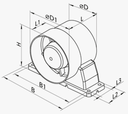
| Parameter | Value | Measurement unit |
|---|---|---|
| Ø D | 125 | mm |
| Ø D1 | 129 | mm |
| B | 185 | mm |
| B1 | 169 | mm |
| H | 139 | mm |
| L | 93 | mm |
| L1 | 31 | mm |
| L2 | 45 | mm |
| L3 | 29 | mm |
Wiring plan
Wiring plan
| Wiring diagram for the fans equipped with a built-in switch | Wiring diagram for the fans without built-in switch |
 |
 |
| Wiring diagram for the fans equipped with a timer / timer, humidity sensor and a built-in switch | Wiring diagram for the fans equipped with a timer / timer with a humidity sensor without built-in switch |
 |
 |
| Wiring diagram for the fans with a light lamp. Separate activation of the fan and the built-in lamp. | Wiring diagram for the fans with a light lamp. Parallel activation of the fan and the built-in lamp. |
 |
 |
| Wiring diagram for the fans with an light lamp and grounding. Separate activation of the fan and the built-in lamp. | Wiring diagram for the fans with a light lamp and grounding. Parallel switching of the fan and the built-in lamp. |
 |
 |
| Wiring diagram for the fans with grounding | |
 |
* - only for fans designed for 12 V rated voltage (specified on the fan casing and packing).
S, S1, S2 - external switches.
Operating logic of the fans with optional equipment
- The fan equipped with a timer is activated by the control voltage supplied to LT input. After the control voltage is disconnected the fan continues operating within the time period within 2 to 30 minutes according to the timer settings. The turn-off delay time is adjusted by turning the respective potentiometer T control knob clockwise to increase and counter-clockwise to reduce it.
- The fan equipped with a timer and humidity sensor is activated by the control voltage supplied to LT input or in case of exceeding the preset humidity threshold value adjustable from ~60% to ~90%. After the control voltage is disconnected or as the humidity level H drops below the set threshold the fan continues operating within the time period within 2 to 30 minutes according to the timer settings. The turn-off delay time and the threshold humidity level are adjusted by turning the control knob of the respective potentiometer T for timer and H for humidity sensor clockwise to increase and counter-clockwise to reduce the set value. To set the maximum humidity level (90%) set the potentiometer control knob for H max position.
- The fan equipped with a timer and motion sensor is activated in case of the moving detection at the distance from 1 m to 4 m with 100° detection angle. After motion is off the fan continues operating within the time period within 2 to 30 minutes according to the timer settings. The turn-off delay time is adjusted by turning the respective potentiometer T control knob clockwise to increase and counter-clockwise to reduce it.
- Wiring diagram for connection of the light lamp to the fan timer operated by the common switch is shown on diagram 4. Upon the light lamp disconnection the fan continues operating according to the timer setting within the set time period.
Legend
Legend
| Picture symbol | Designation | Modification description | ||
|---|---|---|---|---|
| VKOk | Fan with a fixing bracket for flat surface mounting. | |||
 |
VKO L | The motor is equipped with ball bearings for long service life (appr. 40 thousand hours) and fan mounting at any angle. The bearings are maintenance-free and contain enough grease for the entire operating period. | ||
 |
VKO turbo | High-powered motor. | ||
 |
VKO press | 5-blade low-noise impeller with improved aerodynamics for higher fan capacity. | ||
 |
VKO 12 | Modification with low-voltage motor. 12 V AC power supply. |
Example of installation
Example of installation

BIM
BIM

Accessories