Domestic fans
  Industrial and commercial fans
  Single-room ventilation systems with heat recovery
  Air handling units
  Air heating systems
  Air sterilizers
  Smoke extraction and ventilation
  Accessories for ventilating systems
  Electrical accessories
  Ventilation ducts and fittings
  Air distribution components
  Ventilation kits and vents
 VENTS VK 125 Q
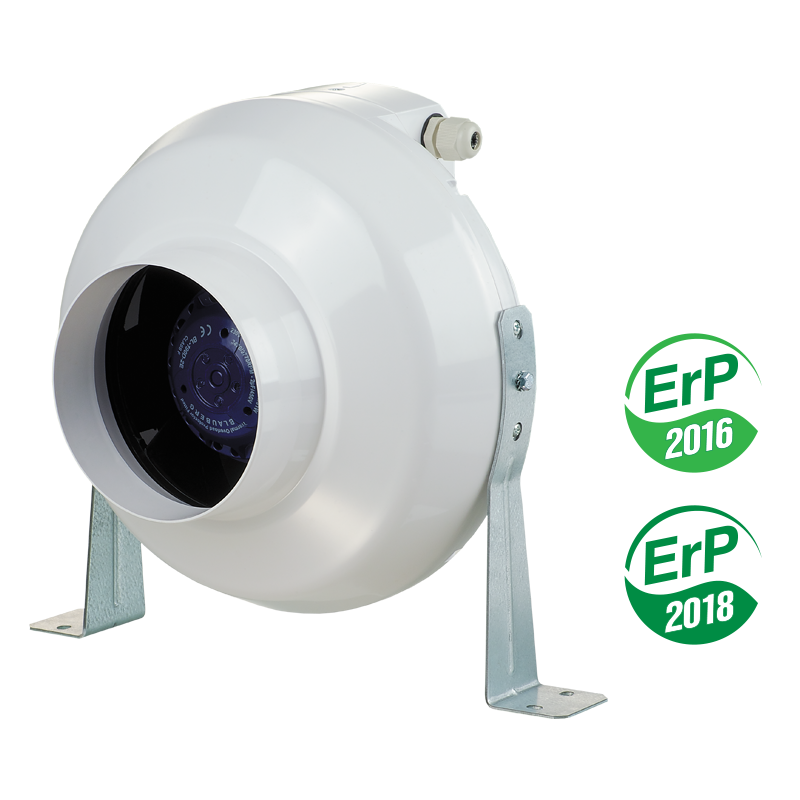
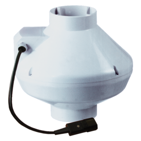

Inline centrifugal fan in plastic casing with the air flow up to 270 m³/h.
- Description
- Characteristics
- Capacity diagram
- Downloads
- Dimensions
- ADDITIONAL TECHNICAL DATA
- Designation key
- Video
Description
Description
| APPLICATIONS | |
|
|
| DESIGN | |
|
|
| MOTOR | |
|
|
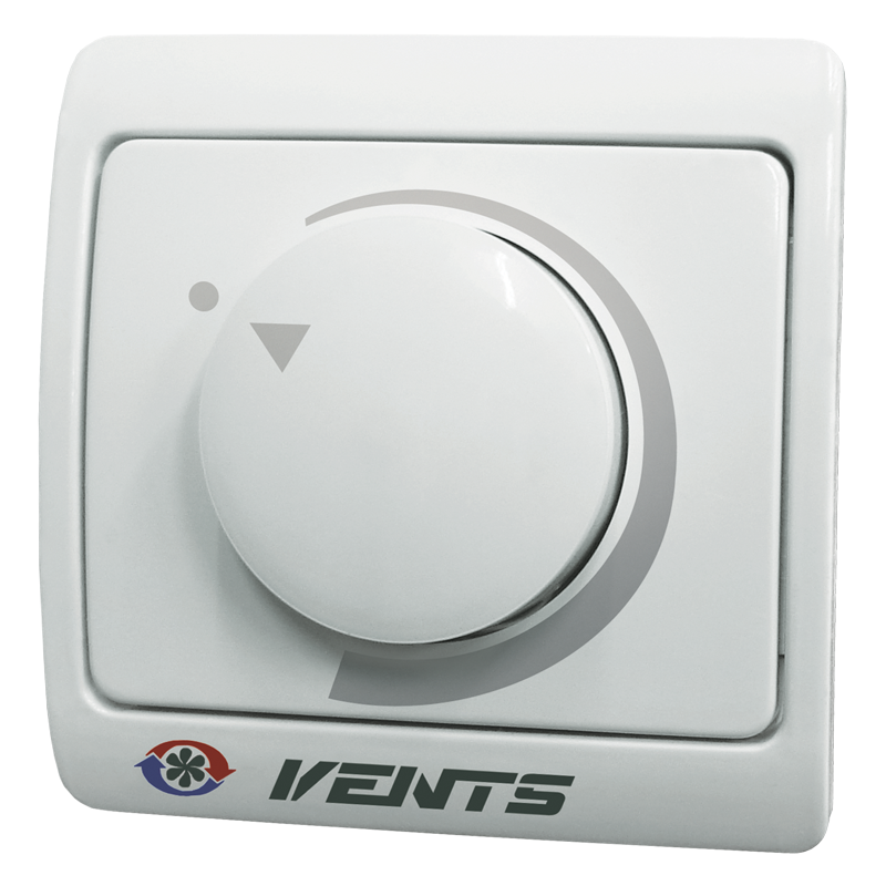
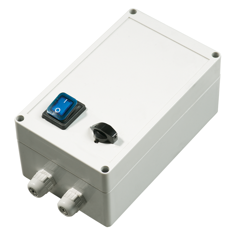
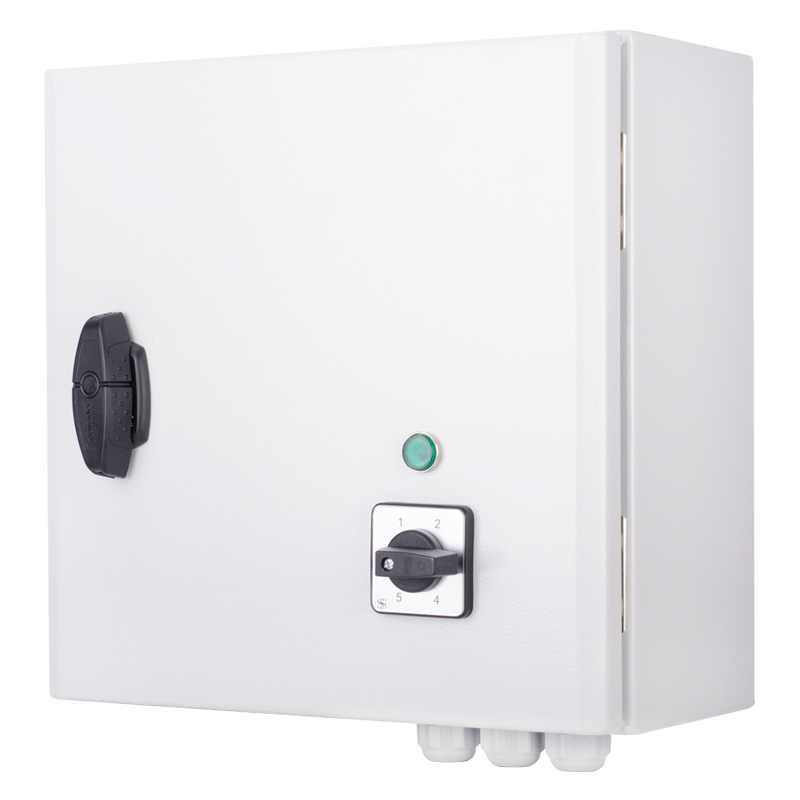
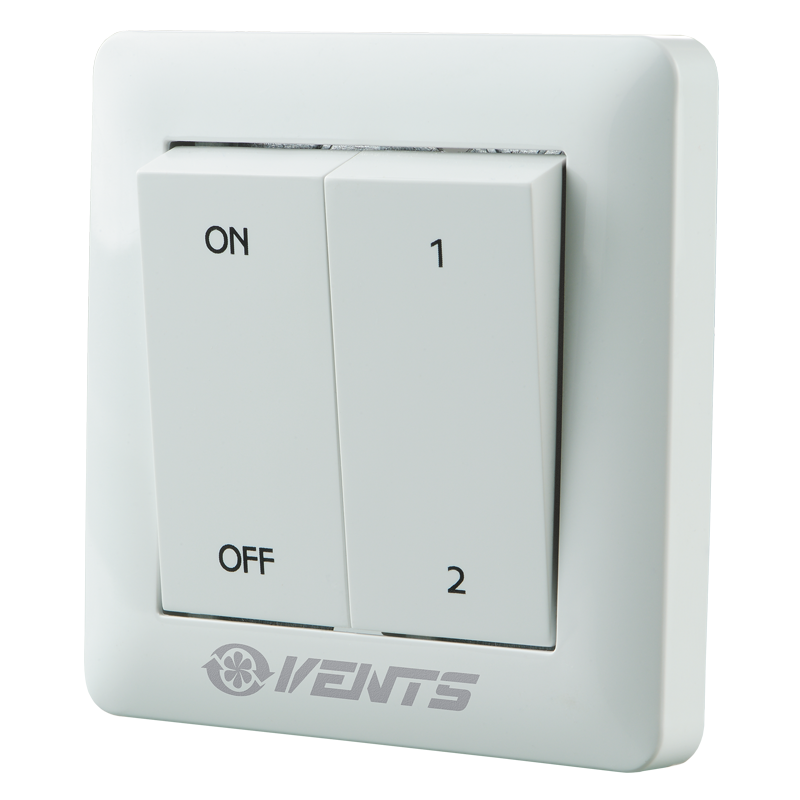
| SPEED CONTROL | |
|
|
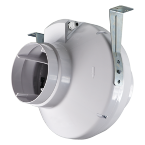
| MOUNTING |
VK fan kitchen exhaust ventilation example |
|
|
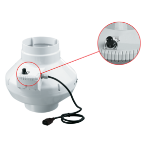
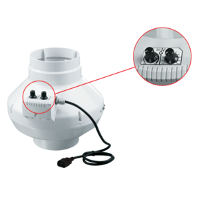
| THE FAN WITH ELECTRONIC TEMPERATURE AND CONTROL MODULE (U OPTION). | |
|
|
| CONTROL LOGIC OF THE FAN WITH THE ELECTRONIC TEMPERATURE AND SPEED CONTROL MODULE | |
|
|
| There are two switch delay patterns for various cases: | |
|
|
| Example for temperature sensor delay pattern: | Example for timer delay pattern: |
|
|
|
|
| ↓ | ↓ |
|
|
| ↓ | ↓ |
|
|
| ↓ | ↓ |
|
|
| ↓ | ↓ |
|
|
| ↓ | |
|
|
| ↓ | |
|
|
| ↓ | |
|
|
|
|

Characteristics
Characteristics
| Parameter |
VK 125 Q 50 Hz |
VK 125 Q 60 Гц |
Measurement unit |
|---|---|---|---|
| Frequency | 50 | 60 | Hz |
| Phase | 1 | 1 | ˜ |
| Voltage | 230 | 230 | V |
| Power | 61 | 64 | W |
| Current | 0.38 | 0.4 | A |
| Sound pressure level at 3 m distance | 36 | 37 | dBА |
| Maximum air capacity | 260 | 270 | m³/h |
| EC motor | no | no | - |
| RPM | 2610 | 2680 | min-1 |
| Protection rating | IP X4 | IP X4 | - |
| Design | centrifugal | centrifugal | - |
| Duct diameter | 125 | 125 | mm |
| Casing material | plastic | plastic | - |
| Width | 270 | 270 | mm |
| Weight | 2.2 | 2.2 | kg |
| Height | 250 | 250 | mm |
| SEC Class | C | - | - |
| Outdoor mounting | no | no | - |
| Sound-insulated casing | no | no | - |
| Duct | for round air ducts | for round air ducts | - |
| Type | exhaust, supply | exhaust, supply | - |
| Mounting | Inline | Inline | - |
| * | To meet the requirements of ErP 2018, a speed controller and local demand control typology must be applied (connect a sensor). | To meet the requirements of ErP 2018, a speed controller and local demand control typology must be applied (connect a sensor). | - |
Capacity diagram
Capacity diagram
- Selection method:
- Air flow:
- Pressure:
Operating point
- Air flow: --
- Pressure: ---
Files archieve
Downloads
Select document type
Dimensions
Characteristics
| Parameter | Value | Measurement unit |
|---|---|---|
| ∅D | 125 | mm |
| ØD1 | 250 | mm |
| B | 270 | mm |
| L | 220 | mm |
| L1 | 30 | mm |
| L2 | 27 | mm |
| L3 | 30 | mm |
ADDITIONAL TECHNICAL DATA
ADDITIONAL TECHNICAL DATA
| Sound-power level, A - weighted | Octave-frequency band [Hz] | LpA, 3 m dBA | LpA, 1 m dBA | |||||||||
| Hz | Gen. | 63 | 125 | 250 | 500 | 1000 | 2000 | 4000 | 8000 | |||
| LwA to inlet | dBA | 78 | 52 | 70 | 76 | 67 | 63 | 60 | 55 | 46 | 57 | 67 |
| LwA to outlet | dBA | 77 | 59 | 70 | 75 | 66 | 60 | 58 | 53 | 45 | 56 | 66 |
| LwA to environment | dBA | 56 | 27 | 40 | 48 | 51 | 50 | 50 | 40 | 28 | 36 | 46 |
Designation key
Designation key
| Series | Duct diameter [mm] | Options | |
| VENTS VK | S: high-powered motor | 100; 125; 150*; 200; 250; 315 |
Q: low-powered motor. Duo: double-speed motor. U: speed controller with electronic thermostat and temperature sensor integrated into the air duct. Equipped with power cord and IEC C14 electric plug. Temperature-based operation logic. Un: speed controller with electronic thermostat and external temperature sensor fixed on 4 m cable. Equipped with power cord and IEC C14 electric plug. Temperature-based operation logic. U1: speed controller with electronic thermostat and temperature sensor integrated into the air duct. Equipped with power cord and IEC C14 electric plug. Timer-based operation logic. U1n: speed controller with electronic thermostat and external temperature sensor fixed on 4 m cable. Equipped with power cord and IEC C14 electric plug. Timer-based operation logic. P: built-in smooth speed controller and power cord with IEC C14 electric plug. V: built-in speed switch (for models with double-speed motors). R: power cord with IEC C14 electric plug. |
* VK 150 model is compatible with the air ducts both Ø 150 and 160 mm
Video
Video
Accessories